This lesson will show us how to display letters and characters to the screen. A vector font format would be ideal, but would also be difficult to implement, so this lesson uses a bitmap font. I will choose Liberation Mono from the download page for my font. There are also two ways to do the length of the string. The function can work until it meets a null operator, or it can establish the length of the string first, and then the characters. This code does the latter. This code will display our command line text.
Drawing.s:
/*Sets where and what we draw*/
.section .data
.align 1
foreColour: /*color shapes will be drawn in*/
.hword 0xFFFF
.align 2
graphicsAddress: /*address of framebuffer*/
.int 0
.align 4
font: /*copies font data into address .align 4 ensures characters start on a multiple of 16 bytes*/
.incbin “font.bin”
.section .text
.globl SetForeColour
SetForeColour: /*changes color to color in r0*/
cmp r0,#0x10000
movhs pc,lr
ldr r1,=foreColour
strh r0,[r1]
mov pc,lr
.globl DrawCharacter
DrawCharacter: /*displays the character given in r0 to the screen*/
cmp r0,#127
movhi r0,#0
movhi r1,#0
movhi pc,lr
push {r4,r5,r6,r7,r8,lr}
x .req r4
y .req r5
charAddr .req r6
mov x,r1 /*r1, r2 gives the left corner of the character*/
mov y,r2
ldr charAddr,=font
add charAddr, r0,lsl #4
lineLoop$:
bits .req r7
bit .req r8
ldrb bits,[charAddr]
mov bit,#8
width .req r0 /*width of printed character*/
height .req r1 /*height of printed character*/
mov width,#8
mov height,#16
pop {r4,r5,r6,r7,r8,pc}
.unreq width
.unreq height
.globl DrawString
DrawString: /*displays the image for the string of character in r0 to the screen*/
x .req r4
y .req r5
x0 .req r6
string .req r7
length .req r8
char .req r9
push {r4,r5,r6,r7,r8,r9,lr}
.section .text
.globl FindTag
FindTag: /*finds addresses of all tags and returns address of the tag that r0 indicates*/
tag .req r0
tagList .req r1
tagAddr .req r2
mov r0,#9 /*finds command line tag and draws everything in it*/
bl FindTag
ldr r1,[r0]
lsl r1,#2
sub r1,#8
add r0,#8
mov r2,#0
mov r3,#0
bl DrawString
loop$:
b loop$
This lesson will show us how to draw lines on the screen. It uses the Bresenham’s Line Algorithm to figure out how to draw the line because it does not use division, and as I have discussed before, using division for an operating system can cause it to be very slow. It also has a function to simulate random numbers so that lines will be drawn from the point the previous line ended to a new apparently “random” point. It is never truly random but will appear random to the observer.
Here is drawing.s:
/*Sets where and what we draw*/
.section .data
.align 1
foreColour: /*color shapes will be drawn in*/
.hword 0xFFFF
.align 2
graphicsAddress: /*address of framebuffer*/
.int 0
.section .text
.globl SetForeColour
SetForeColour: /*changes color to color in r0*/
cmp r0,#0x10000
movhs pc,lr
ldr r1,=foreColour
strh r0,[r1]
mov pc,lr
lastRandom .req r7 /*set aliases on registers so we can tell what we are changing/doing as there are a lot of registers used here. it would be hard to keep track otherwise*/
lastX .req r8
lastY .req r9
colour .req r10
x .req r5
y .req r6
mov lastRandom,#0
mov lastX,#0
mov r9,#0
mov r10,#0
render$: /*1 loop creates a line*/
mov r0,lastRandom
bl Random /*generates x coordinate*/
mov x,r0
bl Random /*generates y coordinate, uses x as input*/
mov y,r0
mov lastRandom,r0 /*updates last random number*/
This lesson starts off by explaining graphics and color systems. We will use the High Color system. We start by programming 2 methods, MailboxRead and MailboxWrite. These will allow us to communicate with the frame buffer.
mailbox.s:
.globl GetMailboxBase
GetMailboxBase: /*gets address of mailbox and puts it into r0*/
ldr r0,=0x2000B880
mov pc,lr
.globl MailboxWrite
MailboxWrite:
tst r0,#0b1111 /*computes the and operation of r0 and #0b1111 and compares it to 0. checks that the lowest 4 bits in r0 are all 0*/
movne pc,lr
cmp r1,#15
movhi pc,lr
channel .req r1 /*creates aliases so the registers cannot be overwritten*/
value .req r2
mov value,r0
push {lr} /*pushes link register into stack so it cannot be overwritten*/
bl GetMailboxBase /*calls GetMailboxBase*/
mailbox .req r0
wait1$:
status .req r3
ldr status,[mailbox,#0x18] /*loads the current status*/
tst status,#0x80000000 /*checks that the top bit of status is 0 and loops back if not*/
.unreq status
bne wait1$
add value,channel /*adds channel and value*/
.unreq channel
str value,[mailbox,#0x20] /*stores result to the write field*/
.unreq value
.unreq mailbox
pop {pc}
channel .req r1 /*Can’t overwrite r1 or link register and calls GetMailboxBase*/
mov channel,r0
push {lr}
bl GetMailboxBase
mailbox .req r0
rightmail$:
wait2$:
status .req r2
ldr status,[mailbox,#0x18] /*loads current status*/
tst status,#0x40000000 /*and function and compare to 0. checks that the 30th bit is 0*/
.unreq status
bne wait2$ /*loop if not 0*/
mail .req r2
ldr mail,[mailbox,#0] /*reads next mailbox item*/
inchan .req r3
and inchan,mail,#0b1111 /*checks if channel of the mail read is the one supplied*/
teq inchan,channel
.unreq inchan
bne rightmail$ /*if not, loops*/
.unreq mailbox
.unreq channel
and r0,mail,#0xfffffff0 /*moves top 28 bits of mail to r0*/
.unreq mail
pop {pc}
Then we write a request framebuffer.s
.section .data
.align 4 /*ensures lowest 4 bits of address of next line are 0. mailbox only sends values with low 4 bits all 0’s*/
.globl FrameBufferInfo
FrameBufferInfo:
.int 1024 /* #0 Physical Width */ /*physical same as virtual*/
.int 768 /* #4 Physical Height */
.int 1024 /* #8 Virtual Width */
.int 768 /* #12 Virtual Height */
.int 0 /* #16 GPU – Pitch */ /*gpu will fill in number with number of bytes on each row*/
.int 16 /* #20 Bit Depth */ /*this will ensure it uses high colour mode because high colour mode uses 16bits for each pixel*/
.int 0 /* #24 X */ /*number of pixels to skip in top left corner of screen*/
.int 0 /* #28 Y */ /* ^ */
.int 0 /* #32 GPU – Pointer */ /*pointer to framebuffer. filled in by gpu*/
.int 0 /* #36 GPU – Size */ /*size of framebuffer in bytes. filled in by gpu*/
render$:
fbAddr .req r3 /*load in framebufffer address*/
ldr fbAddr,[fbInfoAddr,#32]
colour .req r0
y .req r1
mov y,#768
drawRow$: /*loop to draw every row*/
x .req r2
mov x,#1024
drawPixel$: /*draw every pixel on every row*/
strh colour,[fbAddr] /*stores pixel’s color*/
add fbAddr,#2
sub x,#1
teq x,#0
bne drawPixel$
sub y,#1
add colour,#1 /*color change every row*/
teq y,#0
bne drawRow$
b render$ /*loops to beginning after drawing full screen*/
.unreq fbAddr
.unreq fbInfoAddr
Here is a video of the first test, where it works correctly:
This lesson is to flash SOS in Morse code. However, I’ve already done this so I will go through the lesson and improve on my code.
This code will be much easier than the way I coded it before. It enters a pattern of 1s and 0s which stand for a unit of time that the light is on and a unit of time that the light is off, and the program reads the pattern and flashes it.
Looking at the pattern, I believe that to be wrong. What it looks like is a 1 turns the pin on, which turns the light off, and a 0 turns the pin off, which turns the light on. This means the pattern starts with the light off then does the …—… pattern. By this pattern, the .’s are 1/4th of a second and the -‘s are 3/4 of a second. There is 1/4 of a second between each . and –
I edited the main.s file to this:
.section .init /*Tells which code to read*/
.globl _start
_start:
b main
ptrn .req r4 /*puts alias on r4*/
ldr ptrn,=pattern /*loads the pattern into r4*/
ldr ptrn,[ptrn]
seq .req r5 /*puts alias on r5. this will keep track of how much of the pattern has been displayed*/
mov seq,#0 /*loads 0 into r5. starts with none of the pattern displayed yet*/
loop$: /*labels next line for the loop*/
pinNum .req r0
pinVal .req r1
mov pinNum,#16 /* */
mov pinVal,#1 /*change to #1 to turn pin on and turn light off*/
lsl r1,seq /*shifts r1 left the number of places that the pattern has displayed so far*/
and r1,ptrn /*loads into r1 only what is left of the pattern*/
bl SetGpio /*runs function SetGpio*/
.unreq pinNum
.unreq pinVal
/*The new wait function. Number in r0 is how many microseconds it will wait. This is now 1/4th of a second wait*/
ldr r0,=250000
bl Wait
add seq,#1 /*moves to next place in the sequence*/
and seq,#0b11111 /*when seq hits 32, its anded with 11111, which will set it back to 0*/
b loop$ /* go back to start of the loop for an indefinite loop*/
.section .data
.align 2 /*places at address that is the second power of 2. will be placed at a multiple of 4*/
pattern: /*labels data as pattern*/
.int 0b11111111101010100010001000101010 /*copies to output directly*/
However, I dont like the way this looks at all. It does do some sort of pattern, but it does not look like SOS, so something is wrong. I looked at the download of the main.s and found that I had messed up with a couple of aliases, but that was not the problem. I tested with my main.s file and the downloaded function files, and I was still having the problem, so the problem must be in my main.s file. I am going to remove my aliases so that I can better compare it to the downloadable file and see what went wrong.
After removing the aliases, it worked fine so the problem must have been with the aliases.
Here is the main.s code:
.section .init /*Tells which code to read*/
.globl _start
_start:
b main
.section .text
main:
mov sp,#0x8000
/*enables output to OK LED*/
mov r0,#16
mov r1,#1
bl SetGpioFunction /*runs SetGpioFunction*/
ptrn .req r4 /*puts alias on r4*/
ldr ptrn,=pattern /*loads the pattern into r4*/
ldr ptrn,[ptrn]
seq .req r5 /*puts alias on r5. this will keep track of how much of the pattern has been displayed*/
mov seq,#0 /*loads 0 into r5. starts with none of the pattern displayed yet*/
loop$: /*labels next line for the loop*/
mov r0,#16 /* */
mov r1,#1 /*change to #1 to turn pin on and turn light off*/
lsl r1,seq /*shifts r1 left the number of places that the pattern has displayed so far*/
and r1,ptrn /*loads into r1 only what is left of the pattern*/
bl SetGpio /*runs function SetGpio*/
/*The new wait function. Number in r0 is how many microseconds it will wait. This is now 1/4th of a second wait*/
ldr r0,=250000
bl Wait
add seq,#1 /*moves to next place in the sequence*/
and seq,#0b11111 /*when seq hits 32, its anded with 11111, which will set it back to 0*/
b loop$ /* go back to start of the loop for an indefinite loop*/
.section .data
.align 2 /*places at address that is the second power of 2. will be placed at a multiple of 4*/
pattern: /*labels data as pattern*/
.int 0b11111111101010100010001000101010 /*copies to output directly*/
This works well, and is a much more efficient code than the SOS code that I had before. This concludes the Baking Pi OK lesson series.
This lesson starts off talking about functions, the ABI standard that they must meet for every assembly language so that programmers can understand each other’s work, and reusable code. It explains what the registers need to be used for and what a stack is.
2. Our first function
First I must make a new assembly file called gpio.s so that I can make a function to output the GPIO address. This file goes in the same source folder as main.s.
.globl makes the function accessible to all files
lr contains the address we have to go back to, and pc contains the address of the next instruction to be run. we copied lr into pc so the next instruction to be run is the one we have to go back to. This code would be run by a special branch bl which updates lr to the address of the line after the branch, and then branches to the label.
3. A big function
The GetGpioFunction checks that r0 <= 53 and r1 <= 7. If r0 was greater than 53, the comparison of r1 would not execute and the movhi would. If r0 is less than 53, it checks r1. If it’s greater, the movhi runs. If the mov hi does not run, then we know that r0 <=53 and r1 <= 7.
lr is moved into the stack so lr can be reused, the value of r0 is put into r2 before r0 is overwritten, and GetGpioAddress is run. We know that r0 is the GPIO address, r1 is the function, and r2 is the GPIO pin number. Now we need to figure out which block of 10 the pin number is in through repeated subtraction, as that will be quicker than division for this.
The function loop will keep looping until r2 is between 0 and 9. This effectively divides it by 10 and finds the remainder. 4 is added to the address every time the function loops because the address is in blocks of 4 bytes.
Multiplication by 2 in binary is the same as shifting it left one place, so multiplication by 3 is the same as adding r2 and r2 lsl #1
4. Another function
Now we will write a function to turn a pin off and on. r0 is the pin number and r1 is the pin value. If the value is 0, we want the pin turned off and if it is not 0 we want it on.
An alias is like a label for a register.
The GPIO controller has 2 sets of 4 bytes each for turning pins off and on. The first set in each is the first 32 pins, and the second set is the last 22 pins. Division by 32 is the same as shifting a binary number right 5 places.
teq is test equal
This is the gpio.s that I end up with:
.globl GetGpioAddress /*makes accessible to all files*/
GetGpioAddress: /*function label*/
ldr r0,=0x20200000 /*stores GPIO address in r0*/
mov pc,lr /*copies lr into pc*/
.globl SetGpioFunction
SetGpioFunction:
cmp r0,#53 /*compares r0 to 53*/
cmpls r1,#7 /*compare r1 to 7 only if r0 was <=53*/
movhi pc,lr /*Go back to code that ran the function if r1 > 7*/
push {lr} /*puts value of lr into stack so lr can be used again*/
mov r2,r0 /*move value of r0 to r2 before r0 is overwritten*/
bl GetGpioAddress /*run GetGpioAddress*/
functionLoop$:
cmp r2,#9 /*Compares r2 to 9*/
subhi r2,#10 /*subtract 10 from r2 if r2>9*/
addhi r0,#4 /*add 4 to r0 if r2>9*/
bhi functionLoop$ /*loops if r2>9*/
add r2, r2,lsl #1 /*multiplication by 3*/
lsl r1,r2 /*shifts r1 left the number that r2 was just calculated to be*/
str r1,[r0] /*stores computed function address at address in gpio controller*/
pop {pc} /*pops value of lr that was in pc. same as move pc,lr*/
globl SetGpio
SetGpio:
pinNum .req r0 /*alias to refer to r0*/
pinVal .req r1 /*alias to refer to r1*/
cmp pinNum,#53 /*checks if its a valid pin number*/
movhi pc,lr /*copies lr to pc if it’s not a valid pin number*/
push {lr} /*lr pushed into stack so it can be used again*/
mov r2,pinNum /*pin number moved to r2*/
.unreq pinNum /*removes alias from r0*/
pinNum .req r2 /*puts pin number alias on r2*/
bl GetGpioAddress /*run GetGpioAddress*/
gpioAddr .req r0 /*puts alias on r0*/
pinBank .req r3 /*puts alias on r3*/
lsr pinBank,pinNum,#5 /*division by 32*/
lsl pinBank,#2 /*multiplication by 4*/
add gpioAddr,pinBank /*adds either 28 or 40 to the address. this will turn it on or off*/
.unreq pinBank /*removes alias from r3*/
and pinNum,#31 /*pinNum modular 32*/
setBit .req r3 /* alias on r3*/
mov setBit,#1 /*sets r3 to #1*/
lsl setBit,pinNum /*shifts r3 left the value computed by modular 32*/
.unreq pinNum /*removes alias from r2*/
teq pinVal,#0 /*checks if pinVal and #0 are the same*/
.unreq pinVal /*removes alias from rr1*/
streq setBit,[gpioAddr,#40] /*turns pin off if pinVal is 0 by storing setbit at 40 away from address*/
strne setBit,[gpioAddr,#28] /*turns pin on if pinVal is not 0 by storing setbit at 28 away from address*/
.unreq setBit /*remove alias from r3*/
.unreq gpioAddr /*remove alias from r0*/
pop {pc} /*pops whatever is in pc, which is lr*/
Now I need to edit my main.s to use the functions. The .text section is introduced which must come after the .init section. I will also rewrite the wait code to use what I have learned. Here is my new main.s:
.section .init /*Tells which code to read*/
.globl _start
_start:
b main
/* turns light on*/
loop$: /*labels next line for the loop*/
pinNum .req r0
pinVal .req r1
mov pinNum,#16 /* */
mov pinVal,#0 /*change to #1 to turn pin on and turn light off*/
bl SetGpio /*runs function SetGpio*/
.unreq pinNum
.unreq pinVal
/* Creates the delay in the same way as before by subtracting from 3F0000, but uses what we just learned this time */
base .req r0 /*creates alias for r0*/
mov base,#0x3F0000 /*sets r0 to 3F0000*/
wait1$: /*label to start wait loop*/
sub base,#1 /*subtract 1 from base*/
teq base,#0 /*check if base equals 0*/
bne wait1$ /*repeat loop if they do not equal*/
.unreq base /*remove alias*/
/* wait again*/
base .req r0
mov base,#0x3F0000
wait2$:
sub base,#1
teq base,#0
bne wait2$
.unreq base
/* go back to start of the loop for an indefinite loop*/
b loop$
And now I will post of video of what happens:
However, I seem to be getting this error when I try to do the make:
mkdir build

arm-none-eabi-as -I source/ source/gpio.s -o build/gpio.o

make: *** No rule to make target `build/', needed by `build/main.o'.  Stop.
I’m getting this error even after checking that I am in the right directory and trying with the downloaded solutions from the site. I found this thread which seems to be about the same error: http://www.raspberrypi.org/phpBB3/viewtopic.php?f=72&t=57164 This suggests that the error is with yagarto’s makefile. So now I guess I will try to get MinGW working as it suggests in the thread. Alternatively, I might need to change the makefile if I can find the proper way to fix the error.
I found a makefile that was slightly changed and a file called libcsud.a which needed to be in the folder for it to work and now it works fine.
So now I will test my programs and show a video of the light blinking:
This works so now I will do the light blinking fast and slow by changing the values of 3F0000 to 1F0000 and 7F0000. This will be in the main file as I do not need to change the functions. There are only 2 places where this number needs to be changed, 1 in each wait.
Fast:
.section .init /*Tells which code to read*/
.globl _start
_start:
b main
/* turns light on*/
loop$: /*labels next line for the loop*/
pinNum .req r0
pinVal .req r1
mov pinNum,#16 /* */
mov pinVal,#0 /*change to #1 to turn pin on and turn light off*/
bl SetGpio /*runs function SetGpio*/
.unreq pinNum
.unreq pinVal
/* Creates the delay in the same way as before by subtracting from 3F0000, but uses what we just learned this time */
base .req r0 /*creates alias for r0*/
mov base,#0x1F0000 /*sets r0 to 1F0000*/
wait1$: /*label to start wait loop*/
sub base,#1 /*subtract 1 from base*/
teq base,#0 /*check if base equals 0*/
bne wait1$ /*repeat loop if they do not equal*/
.unreq base /*remove alias*/
/* turns light on*/
loop$: /*labels next line for the loop*/
pinNum .req r0
pinVal .req r1
mov pinNum,#16 /* */
mov pinVal,#0 /*change to #1 to turn pin on and turn light off*/
bl SetGpio /*runs function SetGpio*/
.unreq pinNum
.unreq pinVal
/* Creates the delay in the same way as before by subtracting from 3F0000, but uses what we just learned this time */
base .req r0 /*creates alias for r0*/
mov base,#0x7F0000 /*sets r0 to 7F0000*/
wait1$: /*label to start wait loop*/
sub base,#1 /*subtract 1 from base*/
teq base,#0 /*check if base equals 0*/
bne wait1$ /*repeat loop if they do not equal*/
.unreq base /*remove alias*/
/* turns light on*/
loopDot1$: /*labels next line for the loop*/
pinNum .req r0
pinVal .req r1
mov pinNum,#16 /* */
mov pinVal,#0 /*change to #1 to turn pin on and turn light off*/
bl SetGpio /*runs function SetGpio*/
.unreq pinNum
.unreq pinVal
/* Creates the delay in the same way as before by subtracting from 3F0000, but uses what we just learned this time */
base .req r0 /*creates alias for r0*/
mov base,#0x3F0000 /*sets r0 to 3F0000*/
waitDot1$: /*label to start wait loop*/
sub base,#1 /*subtract 1 from base*/
teq base,#0 /*check if base equals 0*/
bne waitDot1$ /*repeat loop if they do not equal*/
.unreq base /*remove alias*/
/* wait again*/
base .req r0
mov base,#0x3F0000
waitDot2$:
sub base,#1
teq base,#0
bne waitDot2$
.unreq base
sub 3loop,#1
cmp 3loop,#0
bne loopDot1$ /*This will loop 3 times*/
mov 3loop,$3
loopDash$: /*labels next line for the loop*/
pinNum .req r0
pinVal .req r1
mov pinNum,#16 /* */
mov pinVal,#0 /*change to #1 to turn pin on and turn light off*/
bl SetGpio /*runs function SetGpio*/
.unreq pinNum
.unreq pinVal
/* Creates the delay in the same way as before by subtracting from 7F0000, but uses what we just learned this time */
base .req r0 /*creates alias for r0*/
mov base,#0x7F0000 /*sets r0 to 7F0000*/
waitDash1$: /*label to start wait loop*/
sub base,#1 /*subtract 1 from base*/
teq base,#0 /*check if base equals 0*/
bne waitDash1$ /*repeat loop if they do not equal*/
.unreq base /*remove alias*/
/* wait again*/
base .req r0
mov base,#0x7F0000
waitDash2$:
sub base,#1
teq base,#0
bne waitDash2$
.unreq base
sub 3loop,#1
cmp 3loop,#0
bne loopDash$ /*This will loop 3 times*/
mov 3loop,$3
loopDot2$: /*labels next line for the loop*/
pinNum .req r0
pinVal .req r1
mov pinNum,#16 /* */
mov pinVal,#0 /*change to #1 to turn pin on and turn light off*/
bl SetGpio /*runs function SetGpio*/
.unreq pinNum
.unreq pinVal
/* Creates the delay in the same way as before by subtracting from 3F0000, but uses what we just learned this time */
base .req r0 /*creates alias for r0*/
mov base,#0x3F0000 /*sets r0 to 3F0000*/
waitDot3$: /*label to start wait loop*/
sub base,#1 /*subtract 1 from base*/
teq base,#0 /*check if base equals 0*/
bne waitDot3$ /*repeat loop if they do not equal*/
.unreq base /*remove alias*/
/* wait again*/
base .req r0
mov base,#0x3F0000
waitDot4$:
sub base,#1
teq base,#0
bne waitDot4$
.unreq base
sub 3loop,#1
cmp 3loop,#0
bne loopDot2$ /*This will loop 3 times*/
.unreq 3loop
/*indefinite loop*/
indefLoop$:
b indefLoop$
This gave an error about the alias 3loop so I changed all occurrences of 3loop to Mloop and that worked fine so I guess aliases can’t have numbers in them.
And testing this revealed that it forever blinks at normal speed, so this is wrong. Something must be wrong with my first normal speed loop so that it loops forever instead of 3 times. I went back to my slow blink code and tried to just make that one blink 3 times so it would be smaller and therefore easier to isolate the problem. The problem seems to be using register 3. This is most likely because the functions use register 3, so I changed it to register 4 and it works fine. Now I need to add the rest back in so here is the code of that:
.section .init /*Tells which code to read*/
.globl _start
_start:
b main
loopDot1$: /*labels next line for the loop*/
pinNum .req r0
pinVal .req r1
mov pinNum,#16 /* */
mov pinVal,#0 /*change to #1 to turn pin on and turn light off*/
bl SetGpio /*runs function SetGpio*/
.unreq pinNum
.unreq pinVal
/* Creates the delay in the same way as before by subtracting from 3F0000, but uses what we just learned this time */
base .req r0 /*creates alias for r0*/
mov base,#0x3F0000 /*sets r0 to 3F0000*/
waitDot1$: /*label to start wait loop*/
sub base,#1 /*subtract 1 from base*/
teq base,#0 /*check if base equals 0*/
bne waitDot1$ /*repeat loop if they do not equal*/
.unreq base /*remove alias*/
/*wait again*/
base .req r0
mov base,#0x3F0000
waitDot2$:
sub base,#1
teq base,#0
bne waitDot2$
.unreq base
sub Mloop,#1
teq Mloop,#0
bne loopDot1$
mov Mloop,#3
loopDash$: /*labels next line for the loop*/
pinNum .req r0
pinVal .req r1
mov pinNum,#16 /* */
mov pinVal,#0 /*change to #1 to turn pin on and turn light off*/
bl SetGpio /*runs function SetGpio*/
.unreq pinNum
.unreq pinVal
/* Creates the delay in the same way as before by subtracting from 7F0000, but uses what we just learned this time */
base .req r0 /*creates alias for r0*/
mov base,#0x7F0000 /*sets r0 to 7F0000*/
waitDash1$: /*label to start wait loop*/
sub base,#1 /*subtract 1 from base*/
teq base,#0 /*check if base equals 0*/
bne waitDash1$ /*repeat loop if they do not equal*/
.unreq base /*remove alias*/
/* wait again*/
base .req r0
mov base,#0x7F0000
waitDash2$:
sub base,#1
teq base,#0
bne waitDash2$
.unreq base
sub Mloop,#1
teq Mloop,#0
bne loopDash$
mov Mloop,#3
loopDot2$: /*labels next line for the loop*/
pinNum .req r0
pinVal .req r1
mov pinNum,#16 /* */
mov pinVal,#0 /*change to #1 to turn pin on and turn light off*/
bl SetGpio /*runs function SetGpio*/
.unreq pinNum
.unreq pinVal
/* Creates the delay in the same way as before by subtracting from 3F0000, but uses what we just learned this time */
base .req r0 /*creates alias for r0*/
mov base,#0x3F0000 /*sets r0 to 3F0000*/
waitDot3$: /*label to start wait loop*/
sub base,#1 /*subtract 1 from base*/
teq base,#0 /*check if base equals 0*/
bne waitDot3$ /*repeat loop if they do not equal*/
.unreq base /*remove alias*/
/*wait again*/
base .req r0
mov base,#0x3F0000
waitDot4$:
sub base,#1
teq base,#0
bne waitDot4$
.unreq base
sub Mloop,#1
teq Mloop,#0
bne loopDot2$
.unreq Mloop
/*indefinite loop*/
indefloop$:
b indefloop$
And this worked, so now I am going to move on to lesson 4, which should be much quicker and just edits the wait function. I will do this with the normal blink first,then the others.
Lesson 4
This rewrites the wait function so that the time can be set. This makes it a lot easier.
Main.s:
.section .init /*Tells which code to read*/
.globl _start
_start:
b main
/* turns light on*/
loop$: /*labels next line for the loop*/
pinNum .req r0
pinVal .req r1
mov pinNum,#16 /* */
mov pinVal,#0 /*change to #1 to turn pin on and turn light off*/
bl SetGpio /*runs function SetGpio*/
.unreq pinNum
.unreq pinVal
/*The new wait function. Number in r0 is how many microseconds it will wait. This is 1 second wait*/
ldr r0,=1000000
bl Wait
This works well, and it is much easier to change how long the wait is, and to call the function. I’ll change the speed so the blink is longer than the wait between blinks, and then I will write my SOS program one last time. I will only need to post my main.s programs for this as I do not need to change the function.
.section .init /*Tells which code to read*/
.globl _start
_start:
b main
/* turns light on*/
loop$: /*labels next line for the loop*/
pinNum .req r0
pinVal .req r1
mov pinNum,#16 /* */
mov pinVal,#0 /*change to #1 to turn pin on and turn light off*/
bl SetGpio /*runs function SetGpio*/
.unreq pinNum
.unreq pinVal
/*The new wait function. Number in r0 is how many microseconds it will wait. This is 2 second wait*/
ldr r0,=2000000
bl Wait
/*The new wait function. Number in r0 is how many microseconds it will wait*/
ldr r0,=100000
bl Wait
/* go back to start of the loop for an indefinite loop*/
b loop$
I will use 1 second for short blinks and 2 seconds for long blinks. I will use half a second between the short blinks and 1 second between the long blinks. Here is the Morse code test:
.section .init /*Tells which code to read*/
.globl _start
_start:
b main
loopDot1$: /*labels next line for the loop*/
pinNum .req r0
pinVal .req r1
mov pinNum,#16 /* */
mov pinVal,#0 /*change to #1 to turn pin on and turn light off*/
bl SetGpio /*runs function SetGpio*/
.unreq pinNum
.unreq pinVal
mov Mloop,#3
loopDash$: /*labels next line for the loop*/
pinNum .req r0
pinVal .req r1
mov pinNum,#16 /* */
mov pinVal,#0 /*change to #1 to turn pin on and turn light off*/
bl SetGpio /*runs function SetGpio*/
.unreq pinNum
.unreq pinVal
loopDot2$: /*labels next line for the loop*/
pinNum .req r0
pinVal .req r1
mov pinNum,#16 /* */
mov pinVal,#0 /*change to #1 to turn pin on and turn light off*/
bl SetGpio /*runs function SetGpio*/
.unreq pinNum
.unreq pinVal
I have a desktop computer, so to start I needed to install a spare card reader I had into my computer, however I found out that my case can’t hold it. So I tried a card reader on a different computer and it would not read my SD card for whatever reason. So I finally purchased a USB card reader and now I am finally ready to get started.
1. Getting started
I read through lesson 0 and it explained the raspberry pi and the programs to download so I downloaded the yagarto file from blackboard and copied the command into the command prompt. Then I went to the raspberry pi website and downloaded the template and extracted that into a new directory on my computer. My SD card came with the required files already on it, so now I am ready to get started.
However, I could not figure out how to do the make. I used the command prompt but was getting errors, so I went back to the website and it said to use minGw so I decided to try that. I tried both mingw and cygwin since I figure I needed some sort of linux command line. Cygwin looked like it might work so I started the lesson.
2. The Beginning
I started by reading the lesson. It says to create a new file in the source folder of the template called main.s so I created a text file and renamed it main.s which changed the file extension to assembler source. I just double clicked it to open it and it tried to open it in visual studio, so I closed that and started editing it with notepad++. I then copied the first three commands in, which don’t actually do anything for the raspberry pi, and are just instructions to the assembler. The first one basically tells it which code to run first and where to put the output and the other 2 prevent a warning message.
3. The First Line
I will copy in my finished code at the end, so I am not going to copy every line of code I write here as I write it. So now I copy in the first line that it says to write which stores a number into register 0. It then explains what registers and hexadecimal numbers are. Registers are small memory locations where you can store numbers. r0 through r12 are general purpose registers. It then explains hexadecimal numbers, which I already know. However I never understood the 0x before the number because when I learned hexadecimal I never used that, so now I know that it is just there to represent that the number is in hexadecimal. The number 2020000016 is actually the address of the GPIO controller, which is why we are storing it in a register.
4. Enabling Output
We are now going to send instructions to the GPIO controller to tell it to turn on the OK LED. The OK LED is wired to the 16th GPIO pin, so we need to enable this pin. We could put a value right in, but we’ll want to change that later so it would be better to use a formula. The # sign before numbers just denotes them as numbers. I used mov instead of ldr to put 1 into register 1 because it is faster. mov is move, ldr is load register, and lsl is logical shift left. These will be useful for me to remember. The second line i just added (the logical shift) will convert the number in register 1 to binary. This will just change 110 to 12. It will then shift the digit over 18 places, giving 10000000000000000002 which can be converted back to 26214410 I opened up a binary to decimal converter to check if this is correct, and it is. The number had to be shifted 18 places because each set of 4 bytes relate to 10 GPIO pins, and then each 3 bits within the 4 byte sections relates to a single pin. So if we need pin 16 we’re in the second section of bytes (10-19) and the 6th section of 3 bits (6×3=18) This all comes from the lesson and is explained very clearly. Finally the last command. str is store register. We store the 10000000000000000002 into the second set of 4 bytes which will be the register of the GPIO controller, r0 + 4.
Now the LED is ready to turn on, so we need to turn the pin off.
5. A Sign of Life
This next three lines are very similar to the ones already written. Put 1 into register 1, shift 1 over 16 places since we need the 16th bit for the 16th pin. Store this into the address needed to turn it off, which is 40 plus the GPIO controller address. 28 would turn the pin on. This sounds very useful when we want the light to blink. We will probably need a loop that turns it off and back on. I could probably find a way for it to wait so long before it turns it off for it to blink slower and make it turn it off faster for it to blink faster. I could probably then make it blink in a rhythm by telling it to turn on and off at certain speeds for each blink instead of making a loop. This could maybe be useful for Morse code since Morse code would be a series of long and short flashes.
6. Happily Ever After
There are three more lines. The first line labels the next line loop$. $ is used generally in labels to differentiate them as labels. The second line is b loop$. The b tells it to execute the line specified, which is loop$, which is the line we are on. This means the code will forever execute this line. This is an infinite loop. The infinite loop keeps the raspberry pi doing something so that it does not crash. The third line is just a blank line which prevents a warning because without it the assembler won’t think that it was truly finished.
7. Pi Time
Now we should be ready to get this onto the Pi and see if it will turn the LED light on as it should.
However, mingw or cygwin will not work. I was getting an error saying that one of the make files was not there even though I checked and it was there. I googled the error and could not find any solutions.
My next idea for a solution was to get oracle virtualbox and just run ubuntu on my computer, as these linux commands would have to work in linux. Virtualbox installed fine, but trying to get ubuntu to install to virtualbox gave me an error saying”kernel requires an x86_64 cpu, but only detected an i686 cpu
unable to boot – please use a kernel appropriate for your cpu”
I then googled this error and found some changes to make to the bios of my computer that should make it work, so I restarted and went into the bios and made those changes. This is where I found it: https://forums.virtualbox.org/viewtopic.php?t=10344
However, I got the exact same error when trying it again so at this point I cannot figure out what could be going wrong.
—————————
I asked a friend how they set up the environment to use the Raspberry Pi and it turns out that I just needed the command prompt. I typed PATH=%PATH%;C:\yagarto\bin and pressed enter then cd c:\RaspberryPi\template and pressed enter to change it to the directory where my source is and then typed make and pressed enter. This was giving me an error before that said
mkdir build/
The syntax of the command is incorrect.
make: *** [build/] Error 1
I was stuck on this for a bit until I realized I needed to completely delete the build directory, and then it was working fine. So I did the make and got the files, renamed the old kernel.img and copied my kernel.img onto the sd card. I’m now ready to put the sd card into the pi and take a video of the results.
This does what it should so now I will start lesson 2 to make the light blink.
This is the main.s file:
.section .init /*Tells which code to read*/
.globl _start
_start:
ldr r0,=0x20200000 /*Stores number into register 0*/
mov r1,#1 /*Puts 1 into register 1*/
lsl r1,#18 /*Shifts the binary representation of the number in register 1 18 places to the left*/
str r1,[r0,#4] /*Stores the number in register 1 at the address given by r0 + 4*/
mov r1,#1 /* Store 1 into register 1*/
lsl r1,#16 /*Shift 1 (binary) over 16 places to the left*/
str r1,[r0,#40] /*Store this binary number into the address to turn pin 16 off (GPIO controller address + 40*/
loop$: /*Labels the next line*/
b loop$ /*Perform the line specified after b (this line). Causes infinite loop*/
Lesson 2
This lesson starts off with a program to wait and explaining what waiting does. This is similar to what I thought I would need to do earlier. I will need to change the time that it waits for if I want to make it blink slower or faster.
It puts the value 3F000016 into register 2 and subtracts 1 from this until it hits 0. This number is 4128768 in base 10, according to a hexadecimal to decimal calculator. This uses the sub command to subtract. cmp compares the result of the subtraction to 0 and bne tells it to go back to the labeled line for a loop if the result of the comparison was that they were not equal to each other.
This sounds like the wait time would be longer or shorter depending on the number put into register 2, so I think if the number is half that, it will blink faster and if the number is twice that then it will blink slower.
2. The All Together
This tells us to turn the light off just like the code to turn it on but with 28 instead of 40, which I commented on earlier. Then it says to set up the code to turn the light on, run the wait code, turn the light off, run the wait code, and loop back to the beginning, and it warns not to reuse labels. It also says it flashes about twice a second which could be changed by the value set to r2, just like I thought. Now I will code it, paste my code, and put a video of what happens.
I just deleted the build folder, did the make again, and copied and replaced the kernel.img file on the sd card.
.section .init /*Tells which code to read*/
.globl _start
_start:
ldr r0,=0x20200000 /*Stores number into register 0*/
mov r1,#1 /*Puts 1 into register 1*/
lsl r1,#18 /*Shifts the binary representation of the number in register 1 18 places to the left*/
str r1,[r0,#4] /*Stores the number in register 1 at the address given by r0 + 4*/
loopBlink$:
mov r1,#1 /* Store 1 into register 1*/
lsl r1,#16 /*Shift 1 (binary) over 16 places to the left*/
str r1,[r0,#40] /*Store this binary number into the address to turn pin 16 off (GPIO controller address + 40)*/
mov r2,#0x3F0000 /*Stores number 3F0000 base 16 into register 2*/
wait1$: /*Label next line*/
sub r2,#1 /*Subtract 1 from 3F0000*/
cmp r2,#0 /*Compare result of subtraction to 0*/
bne wait1$ /*Go back to the subtraction line if the subtraction result does not equal 0*/
mov r1,#1 /* Store 1 into register 1*/
lsl r1,#16 /*Shift 1 (binary) over 16 places to the left*/
str r1,[r0,#28] /*Store this binary number into the address to turn pin 16 off (GPIO controller address + 40)*/
mov r2,#0x3F0000 /*Stores number 3F0000 base 16 into register 2*/
wait2$: /*Label next line*/
sub r2,#1 /*Subtract 1 from 3F0000*/
cmp r2,#0 /*Compare result of subtraction to 0*/
bne wait2$ /*Go back to the subtraction line if the subtraction result does not equal 0*/
b loopBlink$
And this works so now I’m going to change the number in r2 to a smaller number and try to make it blink faster. I will use the Number 1F0000 as I know that is smaller than 3F0000, but I don’t want to make the number too small or the light will blink too fast to be recognizable.
.section .init /*Tells which code to read*/
.globl _start
_start:
ldr r0,=0x20200000 /*Stores number into register 0*/
mov r1,#1 /*Puts 1 into register 1*/
lsl r1,#18 /*Shifts the binary representation of the number in register 1 18 places to the left*/
str r1,[r0,#4] /*Stores the number in register 1 at the address given by r0 + 4*/
loopBlink$:
mov r1,#1 /* Store 1 into register 1*/
lsl r1,#16 /*Shift 1 (binary) over 16 places to the left*/
str r1,[r0,#40] /*Store this binary number into the address to turn pin 16 off (GPIO controller address + 40)*/
mov r2,#0x1F0000 /*Stores number 1F0000 base 16 into register 2*/
wait1$: /*Label next line*/
sub r2,#1 /*Subtract 1 from 1F0000*/
cmp r2,#0 /*Compare result of subtraction to 0*/
bne wait1$ /*Go back to the subtraction line if the subtraction result does not equal 0*/
mov r1,#1 /* Store 1 into register 1*/
lsl r1,#16 /*Shift 1 (binary) over 16 places to the left*/
str r1,[r0,#28] /*Store this binary number into the address to turn pin 16 off (GPIO controller address + 40)*/
mov r2,#0x1F0000 /*Stores number 1F0000 base 16 into register 2*/
wait2$: /*Label next line*/
sub r2,#1 /*Subtract 1 from 1F0000*/
cmp r2,#0 /*Compare result of subtraction to 0*/
bne wait2$ /*Go back to the subtraction line if the subtraction result does not equal 0*/
b loopBlink$
And this works as it should. Now I will increase the number to 5F0000 to make the light blink slower.
.section .init /*Tells which code to read*/
.globl _start
_start:
ldr r0,=0x20200000 /*Stores number into register 0*/
mov r1,#1 /*Puts 1 into register 1*/
lsl r1,#18 /*Shifts the binary representation of the number in register 1 18 places to the left*/
str r1,[r0,#4] /*Stores the number in register 1 at the address given by r0 + 4*/
loopBlink$:
mov r1,#1 /* Store 1 into register 1*/
lsl r1,#16 /*Shift 1 (binary) over 16 places to the left*/
str r1,[r0,#40] /*Store this binary number into the address to turn pin 16 off (GPIO controller address + 40)*/
mov r2,#0x5F0000 /*Stores number 5F0000 base 16 into register 2*/
wait1$: /*Label next line*/
sub r2,#1 /*Subtract 1 from 5F0000*/
cmp r2,#0 /*Compare result of subtraction to 0*/
bne wait1$ /*Go back to the subtraction line if the subtraction result does not equal 0*/
mov r1,#1 /* Store 1 into register 1*/
lsl r1,#16 /*Shift 1 (binary) over 16 places to the left*/
str r1,[r0,#28] /*Store this binary number into the address to turn pin 16 off (GPIO controller address + 40)*/
mov r2,#0x5F0000 /*Stores number 5F0000 base 16 into register 2*/
wait2$: /*Label next line*/
sub r2,#1 /*Subtract 1 from 5F0000*/
cmp r2,#0 /*Compare result of subtraction to 0*/
bne wait2$ /*Go back to the subtraction line if the subtraction result does not equal 0*/
b loopBlink$
While that did work, I want to make it a little more obvious that it is slower before I add a video, so I will change the number to 7F0000, and I will not paste the code.
And this works. So now I am going to try to code it to say something in Morse code. SOS is the most simple thing I can think to make as it is . . . – – – . . . I am going to use the normal flashes as the dots and the slower ones as the dashes, and I will change the dots to the faster flashes if that doesn’t look right to me. The best way I can think to do this is to make the light turn on and off normally and loop that three times, then slowly looped three times, then normally looped three times. However, I have only done infinite loops and the subtraction and comparison. So the way I think I need to do this is to set r3 to #3 and label this line, do the light turn on and off, then subtract 1 from r3, compare, and do bne label. I will do this for each set of three. Also, I need to set r3 before the loop.
Also, since this doesn’t end in an infinite loop, I need to add the infinite loop that I originally had in the first program at the end.
.section .init /*Tells which code to read*/
.globl _start
_start:
ldr r0,=0x20200000 /*Stores number into register 0*/
mov r1,#1 /*Puts 1 into register 1*/
lsl r1,#18 /*Shifts the binary representation of the number in register 1 18 places to the left*/
str r1,[r0,#4] /*Stores the number in register 1 at the address given by r0 + 4*/
mov r3,#3 /*Set r3 to 3*/
loopDot$:
mov r1,#1 /* Store 1 into register 1*/
lsl r1,#16 /*Shift 1 (binary) over 16 places to the left*/
str r1,[r0,#40] /*Store this binary number into the address to turn pin 16 off (GPIO controller address + 40)*/
mov r2,#0x3F0000 /*Stores number 3F0000 base 16 into register 2*/
wait1$: /*Label next line*/
sub r2,#1 /*Subtract 1 from 3F0000*/
cmp r2,#0 /*Compare result of subtraction to 0*/
bne wait1$ /*Go back to the subtraction line if the subtraction result does not equal 0*/
mov r1,#1 /* Store 1 into register 1*/
lsl r1,#16 /*Shift 1 (binary) over 16 places to the left*/
str r1,[r0,#28] /*Store this binary number into the address to turn pin 16 off (GPIO controller address + 40)*/
mov r2,#0x3F0000 /*Stores number 3F0000 base 16 into register 2*/
wait2$: /*Label next line*/
sub r2,#1 /*Subtract 1 from 3F0000*/
cmp r2,#0 /*Compare result of subtraction to 0*/
bne wait2$ /*Go back to the subtraction line if the subtraction result does not equal 0*/
sub r3,#1
cmp r3,#0
bne loopDot$ /*This will loop 3 times*/
mov r3,#3 /*Set r3 to 3*/
loopDash$:
mov r1,#1 /* Store 1 into register 1*/
lsl r1,#16 /*Shift 1 (binary) over 16 places to the left*/
str r1,[r0,#40] /*Store this binary number into the address to turn pin 16 off (GPIO controller address + 40)*/
mov r2,#0x7F0000 /*Stores number 7F0000 base 16 into register 2*/
wait1$: /*Label next line*/
sub r2,#1 /*Subtract 1 from 7F0000*/
cmp r2,#0 /*Compare result of subtraction to 0*/
bne wait1$ /*Go back to the subtraction line if the subtraction result does not equal 0*/
mov r1,#1 /* Store 1 into register 1*/
lsl r1,#16 /*Shift 1 (binary) over 16 places to the left*/
str r1,[r0,#28] /*Store this binary number into the address to turn pin 16 off (GPIO controller address + 40)*/
mov r2,#0x7F0000 /*Stores number 7F0000 base 16 into register 2*/
wait2$: /*Label next line*/
sub r2,#1 /*Subtract 1 from 7F0000*/
cmp r2,#0 /*Compare result of subtraction to 0*/
bne wait2$ /*Go back to the subtraction line if the subtraction result does not equal 0*/
sub r3,#1
cmp r3,#0
bne loopDash$ /*This will loop 3 times*/
mov r3,#3 /*Set r3 to 3*/
loopDot$:
mov r1,#1 /* Store 1 into register 1*/
lsl r1,#16 /*Shift 1 (binary) over 16 places to the left*/
str r1,[r0,#40] /*Store this binary number into the address to turn pin 16 off (GPIO controller address + 40)*/
mov r2,#0x3F0000 /*Stores number 3F0000 base 16 into register 2*/
wait1$: /*Label next line*/
sub r2,#1 /*Subtract 1 from 3F0000*/
cmp r2,#0 /*Compare result of subtraction to 0*/
bne wait1$ /*Go back to the subtraction line if the subtraction result does not equal 0*/
mov r1,#1 /* Store 1 into register 1*/
lsl r1,#16 /*Shift 1 (binary) over 16 places to the left*/
str r1,[r0,#28] /*Store this binary number into the address to turn pin 16 off (GPIO controller address + 40)*/
mov r2,#0x3F0000 /*Stores number 3F0000 base 16 into register 2*/
wait2$: /*Label next line*/
sub r2,#1 /*Subtract 1 from 3F0000*/
cmp r2,#0 /*Compare result of subtraction to 0*/
bne wait2$ /*Go back to the subtraction line if the subtraction result does not equal 0*/
sub r3,#1
cmp r3,#0
bne loopDot$ /*This will loop 3 times*/
infiniteLoop$:
b infiniteLoop$
However, this gave me errors because I forgot to check my variable names. Both blocks of dots use the same loop labels and they all use the same wait labels. So I will change this, post the code and retest.
.section .init /*Tells which code to read*/
.globl _start
_start:
ldr r0,=0x20200000 /*Stores number into register 0*/
mov r1,#1 /*Puts 1 into register 1*/
lsl r1,#18 /*Shifts the binary representation of the number in register 1 18 places to the left*/
str r1,[r0,#4] /*Stores the number in register 1 at the address given by r0 + 4*/
mov r3,#3 /*Set r3 to 3*/
loopDot1$:
mov r1,#1 /* Store 1 into register 1*/
lsl r1,#16 /*Shift 1 (binary) over 16 places to the left*/
str r1,[r0,#40] /*Store this binary number into the address to turn pin 16 off (GPIO controller address + 40)*/
mov r2,#0x3F0000 /*Stores number 3F0000 base 16 into register 2*/
waitDot1$: /*Label next line*/
sub r2,#1 /*Subtract 1 from 3F0000*/
cmp r2,#0 /*Compare result of subtraction to 0*/
bne waitDot1$ /*Go back to the subtraction line if the subtraction result does not equal 0*/
mov r1,#1 /* Store 1 into register 1*/
lsl r1,#16 /*Shift 1 (binary) over 16 places to the left*/
str r1,[r0,#28] /*Store this binary number into the address to turn pin 16 off (GPIO controller address + 40)*/
mov r2,#0x3F0000 /*Stores number 3F0000 base 16 into register 2*/
waitDot2$: /*Label next line*/
sub r2,#1 /*Subtract 1 from 3F0000*/
cmp r2,#0 /*Compare result of subtraction to 0*/
bne waitDot2$ /*Go back to the subtraction line if the subtraction result does not equal 0*/
sub r3,#1
cmp r3,#0
bne loopDot1$ /*This will loop 3 times*/
mov r3,#3 /*Set r3 to 3*/
loopDash$:
mov r1,#1 /* Store 1 into register 1*/
lsl r1,#16 /*Shift 1 (binary) over 16 places to the left*/
str r1,[r0,#40] /*Store this binary number into the address to turn pin 16 off (GPIO controller address + 40)*/
mov r2,#0x7F0000 /*Stores number 7F0000 base 16 into register 2*/
waitDash1$: /*Label next line*/
sub r2,#1 /*Subtract 1 from 7F0000*/
cmp r2,#0 /*Compare result of subtraction to 0*/
bne waitDash1$ /*Go back to the subtraction line if the subtraction result does not equal 0*/
mov r1,#1 /* Store 1 into register 1*/
lsl r1,#16 /*Shift 1 (binary) over 16 places to the left*/
str r1,[r0,#28] /*Store this binary number into the address to turn pin 16 off (GPIO controller address + 40)*/
mov r2,#0x7F0000 /*Stores number 7F0000 base 16 into register 2*/
waitDash2$: /*Label next line*/
sub r2,#1 /*Subtract 1 from 7F0000*/
cmp r2,#0 /*Compare result of subtraction to 0*/
bne waitDash2$ /*Go back to the subtraction line if the subtraction result does not equal 0*/
sub r3,#1
cmp r3,#0
bne loopDash$ /*This will loop 3 times*/
mov r3,#3 /*Set r3 to 3*/
loopDot2$:
mov r1,#1 /* Store 1 into register 1*/
lsl r1,#16 /*Shift 1 (binary) over 16 places to the left*/
str r1,[r0,#40] /*Store this binary number into the address to turn pin 16 off (GPIO controller address + 40)*/
mov r2,#0x3F0000 /*Stores number 3F0000 base 16 into register 2*/
waitDot3$: /*Label next line*/
sub r2,#1 /*Subtract 1 from 3F0000*/
cmp r2,#0 /*Compare result of subtraction to 0*/
bne waitDot3$ /*Go back to the subtraction line if the subtraction result does not equal 0*/
mov r1,#1 /* Store 1 into register 1*/
lsl r1,#16 /*Shift 1 (binary) over 16 places to the left*/
str r1,[r0,#28] /*Store this binary number into the address to turn pin 16 off (GPIO controller address + 40)*/
mov r2,#0x3F0000 /*Stores number 3F0000 base 16 into register 2*/
waitDot4$: /*Label next line*/
sub r2,#1 /*Subtract 1 from 3F0000*/
cmp r2,#0 /*Compare result of subtraction to 0*/
bne waitDot4$ /*Go back to the subtraction line if the subtraction result does not equal 0*/
sub r3,#1
cmp r3,#0
bne loopDot2$ /*This will loop 3 times*/
infiniteLoop$:
b infiniteLoop$
This builds correctly so here is the video of the test.
In this video, the pi gives an initial blink when plugged in and then does what it is supposed to. This concludes my testing for lessons 1 and 2 of the baking pi tutorials.
This lab coincides with section 2.5 of the text. The lab then explained the nslookup tool and how it is run in the command prompt. After explaining nslookup, its syntax and how to understand the result, it asks me to run it and answer a few questions.
1. Run nslookup to obtain the IP address of a Web server in Asia. What is the IP address of that server?
I used google to find a webserver and decided to use the server for AIT Asian Institute of Technology.
The first request timed out, so I did it again and got the IP address 203.159.12.3
This is a non-authoritative answer which the lab explained means the answer came from some other server and not AIT’s server itself. The default server is an eastern server.
2. Run nslookup to determine the authoritative DNS servers for a university in Europe.
I decided to use the Central European University. To determine the authoritative DNS servers, you must use -type=NS like in the second example in the lab.
The primary name server is the authoritative DNS server. It is ns.ceu.hu
3. Run nslookup so that one of the DNS servers obtained in Question 2 is queried for the mail servers for Yahoo! mail. What is its IP address?
In the example in the lab, they typed nslookup server-to-be-lookedup authoritative-server, so I typed nslookup http://www.mail.yahoo.com ns.ceu.hu. However it timed out and all I got was this.
This only provides the IP of the server used, ns.ceu.hu. So, I’m going to flip them around so it uses the server of yahoo mail to lookup ns.ceu.hu so that I get the server’s IP that way.
This gives the IP address 98.139.102.145 Through a quick google search I found this website to look up IP addresses: http://cqcounter.com/whois/ and confirmed that this is a Yahoo! server.
Part 2: ipconfig
This part explains how the ipconfig tool can show TCP/IP information for your host. For example:
This is ALL of the DNS information about my host. ipconfig/displaydns and ipconfig/flushdns can be used to show and clear DNS records obtained by the host.
Part 3 Tracing DNS with Wireshark
I first followed the direction to prepare my browser and DNS cache for packet capture and then captured packets while I went to this page: http://www.ietf.org
Cleared dns cache:
Cleared browser cache. My ipv4 address is listed as 10.33.129.29 by ipconfig, so this is what i filtered by. After the short packet capture, I ended up with 660 packets, many of which were “TCP segment of a reassembled PDU”
4. Locate the DNS query and response messages. Are they sent over UDP or TCP?
They are sent over UDP.
5. What is the destination port for the DNS query message? What is the source port of DNS response message?
The destination port of the query is 53. The source port of the response is also 53.
6. To what IP address is the DNS query message sent? Use ipconfig to determine the IP address of your local DNS server. Are these two IP addresses the same?
As seen in the above picture, the destination of the query is 10.40.4.44 In the ipconfig that I did and pictured earlier, it showed that my local DNS server was 10.40.4.44, so yes they are the same.
7. Examine the DNS query message. What “Type” of DNS query is it? Does the query message contain any “answers”?
The info section calls it a standard query, the list under queries classifies it as type A, and flags shows that it contains no answers.
8. Examine the DNS response message. How many “answers” are provided? What do each of these answers contain?
There was one answer containing the sites address and other information.
9. Consider the subsequent TCP SYN packet sent by your host. Does the destination IP address of the SYN packet correspond to any of the IP addresses provided in the DNS response message?
Yes it does.
10. This web page contains images. Before retrieving each image, does your host issue new DNS queries?
No, there were no new queries before retrieving images.
Now I will do a new packet capture while i do an nslookup of http://www.mit.edu
11. What is the destination port for the DNS query message? What is the source port of DNS response message?
We are supposed to only pay attention to the last of the 3 queries for mit according to the lab, but I have 4 queries, the last 2 appearing very similar so far.
I will pay attention to the first of the last two.
The destination port of the query is 53 and the source port of the response is 53.
12. To what IP address is the DNS query message sent? Is this the IP address of your default local DNS server?
The ip address the query is sent to is 10.40.4.44. We already saw before that this is the address of my local DNS server.
13. Examine the DNS query message. What “Type” of DNS query is it? Does the query message contain any “answers”?
I showed before how to find these answers, so here I will just answer them instead of showing screenshots.
This is a type A standard query, and it contains no answers.
14. Examine the DNS response message. How many “answers” are provided? What do each of these answers contain?
This contains three answers shown here:
15. Provide a screenshot. I already provided this.
Now I repeat this but instead do nslookup -type=NS mit.edu
16. To what IP address is the DNS query message sent? Is this the IP address of your default local DNS server?
This was sent to 10.40.4.44 and this is the IP address of my local DNS server.
17. Examine the DNS query message. What “Type” of DNS query is it? Does the query message contain any “answers”?
This is a standard type NS query and it contains no answers.
18. Examine the DNS response message. What MIT nameservers does the response message provide? Does this response message also provide the IP addresses of the MIT nameservers?
The response message does not contain any nameservers. If it did they would be under additional records right under answers, but there is nothing below answers.
19. Provide a screenshot.
Now I repeat the experiment again but with this command: nslookup http://www.aiit.or.kr bitsy.mit.edu
20. To what IP address is the DNS query message sent? Is this the IP address of your default local DNS server? If not, what does the IP address correspond to?
I tried doing the nslookup 3 times and all of them timed out.
Therefore, I will download the trace files provided in case you can’t run it, and I will answer the questions based on that. This is a screenshot of the downloaded trace:
The query is sent to 18.72.0.3, no this is the ip of the bitsy.mit.edu server.
21. Examine the DNS query message. What “Type” of DNS query is it? Does the query message contain any “answers”?
This is a standard type A query with no answers.
22. Examine the DNS response message. How many “answers” are provided? What do each of these answers contain?
This lab explores aspects of HTTP such as GET/response interaction, and coincides with section 2.2 of the text.
1. I opened a new window, opened Wireshark and filtered by http. Then I waited a minute before I started to capture. I started the capture, opened the link: http://gaia.cs.umass.edu/wireshark-labs/HTTP-wireshark-file1.html and stopped the capture. Here is a screenshot of my captured packets.
Here is the HTTP information for the GET and the response.
GET:
Response:
I now have to answer a few questions.
1. Is your browser running HTTP version 1.0 or 1.1? What version of HTTP is the server running?
Under the first subtab, the GET and response say Request Version: HTTP/1.1 Therefore, both the server and my browser are running HTTP version 1.1
2. What languages (if any) does your browser indicate that it can accept to the server?
I look in the GET message to find out what my computer sent to the server. My browser indicates that it accepts en-us, en.
3. What is the IP address of your computer? Of the gaia.cs.umass.edu server?
My ip address is 10.33.129.16, and the server ip address is 128.119.245.12.
4. What is the status code returned from the server to your browser?
The server sent a 200 OK status code.
5. When was the HTML file that you are retrieving last modified at the server?
Fri, 15 Nov 2013 04:38:01 GMT
6. How many bytes of content are being returned to your browser?
Content-Length: 128\r\n
This means 128 bytes.
7. By inspecting the raw data in the packet content window, do you see any headers within the data that are not displayed in the packet-listing window? If so, name one.
No, I do not see any that are not displayed in the packet-listing window.
Now onto the second part of the lab,
2. Clear the cache in your internet browser, start wireshark, go to this URL:
refresh the page, stop Wireshark, and filter by http.
Here are the screenshots. In order, they are the first GET request, the server response, the second GET request, and the second server response.
Questions:
8. Inspect the contents of the first HTTP GET request from your browser to the server. Do you see an “IF-MODIFIED-SINCE” line in the HTTP GET?
No. This would only show if the site had been visited before.
9.Inspect the contents of the server response. Did the server explicitly return the contents of the file? How can you tell?
Yes it did, it sent the 200 OK message, which means nothing was wrong, and it sent 371 bytes (Content-length).
10. Now inspect the contents of the second HTTP GET request from your browser to the server. Do you see an “IF-MODIFIED-SINCE:” line in the HTTP GET? If so, what information follows the “IF-MODIFIED-SINCE:” header?
Yes, the IF_MODIFIED_SINCE is here because the site has been visited before. The information is: If-Modified-Since: Fri, 15 Nov 2013 05:13:01 GMT\r\n
11. What is the HTTP status code and phrase returned from the server in response to this second HTTP GET? Did the server explicitly return the contents of the file? Explain.
The status code is 304 Not Modified. No the server did not explicitly return the contents of the file, because it was not modified. I can tell because no bytes were sent. (No content-length specified).
Here is the GET request and the multiple packet response:
12. How many HTTP GET request messages did your browser send? Which packet number in the trace contains the GET message for the Bill or Rights?
My browser sent one GET request. There was only one packet.
13. Which packet number in the trace contains the status code and phrase associated with the response to the HTTP GET request?
To figure this out I opened the TCP segments in the packet content window and looked for the one that showed the 200 OK message. This was in the first packet.
14. What is the status code and phrase in the response?
200 OK
15. How many data-containing TCP segments were needed to carry the single HTTP response and the text of the Bill of Rights?
This captured a GET and the response, then 2 GETs for the images and 2 responses. I will not post a picture of each http information, but just one picture of the captured packets:
16. How many HTTP GET request messages did your browser send? To which Internet addresses were these GET requests sent?
My browser sent 3 GET requests. These were sent to 128.119.245.12 & 165.193.140.14 & 128.119.240.90
17. Can you tell whether your browser downloaded the two images serially, or whether they were downloaded from the two web sites in parallel? Explain.
The browser downloaded them serially because there were two separate GETs and they were sent at different times.
I also noticed that the second image was sent in multiple TCP segments, like the one we did before. The second image took 77 packets to send.
18. What is the server’s response (status code and phrase) in response to the initial HTTP GET message from your browser?
401 Authorization Required
19. When your browser’s sends the HTTP GET message for the second time, what new field is included in the HTTP GET message?
The new field is Authorization, with a subtab, credentials. Authorization: Basic d2lyZXNoYXJrLXN0dWRlbnRzOm5ldHdvcms=\r\n
This concludes the second Wireshark lab. This lab has taught me a lot about HTTP GETs and their responses, status codes, how to read http information from the packet sniffer, and some fields that are specific to certain types of http information. It also taught me at the end how to translate the string of characters after authentication from Base64 encoding to ASCII encoding.
P5. Suppose that the UDP receiver computes the Internet checksum for the received UDP segment and finds that it matches the value carried in the checksum field. Can the receiver be absolutely certain that no bit errors have occurred? Explain. The book talks about checksums on page 203. The checksum will detect bit errors if only one occurs, but if multiple occur it may not catch them. So no, the receiver cannot be certain that no bit errors have occurred. An example of a checksum calculation can be found here: http://en.wikibooks.org/wiki/Communication_Networks/TCP_and_UDP_Protocols/UDP#Checksum_Calculation. If the result has a 0 bit in the header, then there is an errors. These errors could include multiple errors cancelling each other out, insertion and deletion of 0’s, and reordering of bytes.
P10. Consider a channel that can lose packets but has a maximum delay that is known. Modify protocol rdt2.1 to include sender timeout and retransmit. Informally argue why your protocol can communicate correctly over this channel.
This is the incorrect receiver protocol that is given for this problem. I need to modify this to include sender timeout and retransmit.
The sender protocol for rdt 2.1 can be found on page 211.
The correct rdt 2.1 receiver protocol can be found on page 212
This protocol would receive retransmitted items the same as it would items that were transmitted and did not time out, so that would look the same. This handles lost packets like corrupted ones.
P15. Consider the cross-country example shown in Figure 3.17. How big would the window size have to be for the channel utilization to be greater than 98 percent? Suppose that the size of a packet is 1,500 bytes, including both header fields and data.
Page 217
dtrans = L/R= (1500*8 bits/packet)/10^9 bits/sec = 1.2×10^-5 seconds or 12 microseconds or 0.012 msec
1500 is in bytes so it must be multiplied by 8 to get bits
t = RTT + L/R = 30.012 msec
In order to calculate for utilization at 98% of the time, we must set .98 = (0.012n)/30.012 where n is the window.
The window is 2450.98 packets, or 2451 packets.
P26. Consider transferring an enormous file of L bytes from Host A to Host B. Assume an MSS of 536 bytes.
a. What is the maximum value of L such that TCP sequence numbers are not exhausted? Recall that the TCP sequence number field has 4 bytes.
The MSS is not important here. The sequence number field is 32 bits, which is 4 bytes (Page 234). Therefore, the maximum value of L would be 2^32 or 4,294,967,296 bits.
b. For the L you obtain in a, find how long it takes to transmit the file. Assume that a total of 66 bytes of transport, network, and data-link header are added to each segment before the resulting packet is sent out over a 155 Mbps link. Ignore flow control and congestion control so A can pump out the segments back to back and continuously.
To find out how long this would take to transmit, we must first figure out how many packets this would need to transmit. The MSS states that we have 536 bytes per packet. 66 of this is taken up by transport, network, and data-link header, so that leaves us with 470 bytes per packet to be used for data. We can now convert our value of L into bytes and divide it by 470 to figure out how many packets we need. 4,294,967,296 bits = 536,870,912 bytes. 536,870,912 bytes / 470 bytes = 1,142,278.53617 packets of data, rounded to 1,142,279 packets. 1,142,279 packets * 536 bytes = 612,261,544 bytes or 4,898,092,352 bits or 4899 Mb. We must transfer 4899 Mb, so we can divide this by the speed 155 Mbps to get the time it will take to transfer in seconds. 4899 Mb/ 155 Mbps = 31.61 seconds.
P40. Consider Figure 3.58. Assuming TCP Reno is the protocol experiencing the behavior shown above, answer the following questions. In all cases, you should provide a short discussion justifying your answer. Page 276 has something similar. Here is the graph:
a. Identify the intervals of time when TCP slow start is operating.
The slow start times are from 1 to 6 and from 23 to 26. These are slow start times because the congestion window size is picking up at a slope, slower at first and becoming exponentially faster until it gets to a linear section and is no longer in slow start.
b. Identify the intervals of time when TCP congestion avoidance is operating.
This is between transmission rounds 6 and 16 and between rounds 17 and 23. This is when it is linearly rising.
c. After the 16th transmission round, is segment loss detected by a triple duplicate ACK or by a timeout?
If it had been a timeout, the congestion window would have dropped to 0 and had a slow start, but neither of those are true so it was detected by a triple ACK.
d. After the 22nd transmission round, is segment loss detected by a triple duplicate ACK or by a timeout?
This one is detected by a timeout for the reasons listed above.
e. What is the initial value of ssthresh at the first transmission round?
The initial value of ssthresh is 33 segments because that is the congestion window size in segments when it starts it’s linear rise which indicates congestion avoidance at transmission round 6. It remains at 33 segments until congestion avoidance ends.
f. What is the value of ssthresh at the 18th transmission round?
The value of ssthresh is set to 0.5*cwnd, which is half of the congestion window at transmission round 16. The transmission window was 43 segments, so the ssthresh is set to 22 segments at the 18th transmission round. This is the congestion window size when it goes into it’s second congestion avoidance phase after the first one ends because it goes into the congestion avoidance phase when it hits ssthresh.
g. What is the value of ssthresh at the 24th transmission round?
The congestion window size at transmission round 23 was 29 segments, so half of this is 15 segments. Therefore, ssthresh is going to be 15 segments at transmission round 24.
h. During what transmission round is the 70th segment sent?
I find this out by adding up the segments that were sent in each transmission round. The congestion window is the segments. So in round 1, 1 segment is sent. Round 2, 2 segments. Round 3, segments 4-8. Round 4, segments 9-17. Round 5, segments 18-34. Round 6, segments 35-67. Round 7, segments 68-101. Therefore, the 70th segment is sent during the 7th transmission round.
i. Assuming a packet loss is detected after the 26th round by the receipt of a triple duplicate ACK, what will be the values of the congestion window size and of ssthresh?
The congestion window size would be 8 segments, and ssthresh would be 4.
j. Suppose TCP Tahoe is used (instead of TCP Reno), and assume that triple duplicate ACKs are received at the 16th round. What are the ssthresh and the congestion window size at the 19th round?
“It is interesting that an early version of TCP, known as TCP Tahoe, unconditionally cut its congestion window to 1 MSS and entered the slow-start phase after either a timeout-indicated or triple-duplicate-ACK-indicated loss event.” (Page 276 of the text) This means that cwnd will be 0 because it has to go through the slow-start state. The ssthresh would be found the same, however, so the current cwnd was 42 segments which makes ssthresh 21.
k. Again suppose TCP Tahoe is used, and there is a timeout event at 22nd round. How many packets have been sent out from 17th round till 22nd round, inclusive?
This means the total number of segments in rounds 17-22 including 22. Round 17: 24 segments. Round 18: 25 segments. Round 19: 26 segments. Round 20: 27 segments. Round 21: 28 segments. Round 22: This would be 29 segments, as the Timeout event occurs here, and in Tahoe this drops the congestion window down to 0 in the next round. This is a total of: 159 packets. This is ignoring the previous timeout/ACK, however. If I don’t ignore the previous one, then it would be in slow start state and would increase exponentially. So, Round 17: 1 packet. 18: 2 packets. 19: 4 packets. 20: 8 packets. 21: 16 packets. 22: 32 packets. This is a total of: 63 packets.
This lab starts off by explaining what Wireshark is, and what a packet sniffer does before it delves into how to get Wireshark. It then walks the reader through downloading and using Wireshark. Here are the steps I went through for the test run:
1. Start up your web browser
2. Start Wireshark
3. Open Capture: Interfaces
4. Select the interface you want to capture packets on (in this case, the one with packets)
9. Select GET message for the web page we displayed and show protocol information for HTTP in the packet-header window
10. Exit Wireshark
This ends the test run.
The lab then asks a series of questions:
1. List 3 different protocols that appear in the protocol column in the unfiltered packet-listing window in step 7 above.
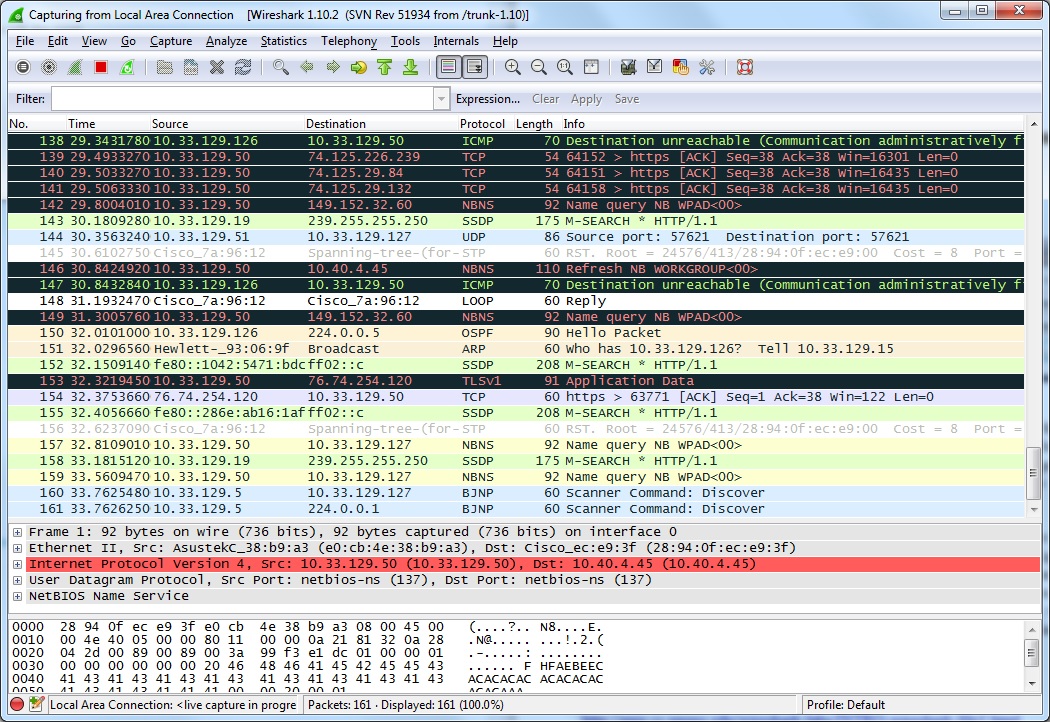
This is the unfiltered list of packets. After the get message, a few different protocols that appear are HTTP, NBNS, TCP, and BROWSER.
2. How long did it take from when the HTTP GET message was sent until the HTTP OK reply was received?
The GET was sent at 21:19:19.439594000 and the OK was received at 21:19:19.475457000, so it took 0.35863 seconds to receive the OK reply.
3. What is the Internet address of the gaia.cs.umass.edu (also known as wwwnet.cs.umass.edu)? What is the Internet address of your computer?
As seen in the above picture, the destination of the GET is the gaia.cs.umass.edu internet address, which is 128.119.245.12, and the source of the GET is my internet address, which is 10.33.129.50.
4. Print the two HTTP messages (GET and OK) referred to in question 2 above. To do so, select Print from the Wireshark File command menu, and select the “Selected Packet Only” and “Print as displayed” radial buttons, and then click OK.
HTTP GET:
No. Time Source Destination Protocol Length Info
1042 21:19:19.439594000 10.33.129.50 128.119.245.12 HTTP 394 GET /wireshark-labs/INTRO-wireshark-file1.html HTTP/1.1
Frame 1042: 394 bytes on wire (3152 bits), 394 bytes captured (3152 bits) on interface 0
Ethernet II, Src: AsustekC_38:b9:a3 (e0:cb:4e:38:b9:a3), Dst: Cisco_ec:e9:3f (28:94:0f:ec:e9:3f)
Internet Protocol Version 4, Src: 10.33.129.50 (10.33.129.50), Dst: 128.119.245.12 (128.119.245.12)
Transmission Control Protocol, Src Port: 64202 (64202), Dst Port: http (80), Seq: 1, Ack: 1, Len: 340
Hypertext Transfer Protocol
GET /wireshark-labs/INTRO-wireshark-file1.html HTTP/1.1\r\n
Host: gaia.cs.umass.edu\r\n
User-Agent: Mozilla/5.0 (Windows NT 6.1; WOW64; rv:24.0) Gecko/20100101 Firefox/24.0\r\n
Accept: text/html,application/xhtml+xml,application/xml;q=0.9,*/*;q=0.8\r\n
Accept-Language: en-US,en;q=0.5\r\n
Accept-Encoding: gzip, deflate\r\n
DNT: 1\r\n
Connection: keep-alive\r\n
\r\n
[Full request URI: http://gaia.cs.umass.edu/wireshark-labs/INTRO-wireshark-file1.html%5D
[HTTP request 1/3]
[Response in frame: 1043]
[Next request in frame: 1044]
HTTP OK:
No. Time Source Destination Protocol Length Info
1043 21:19:19.475457000 128.119.245.12 10.33.129.50 HTTP 409 HTTP/1.1 200 OK (text/html)
Frame 1043: 409 bytes on wire (3272 bits), 409 bytes captured (3272 bits) on interface 0
Ethernet II, Src: Cisco_ec:e9:3f (28:94:0f:ec:e9:3f), Dst: AsustekC_38:b9:a3 (e0:cb:4e:38:b9:a3)
Internet Protocol Version 4, Src: 128.119.245.12 (128.119.245.12), Dst: 10.33.129.50 (10.33.129.50)
Transmission Control Protocol, Src Port: http (80), Dst Port: 64202 (64202), Seq: 1, Ack: 341, Len: 355
Hypertext Transfer Protocol
HTTP/1.1 200 OK\r\n
Date: Wed, 06 Nov 2013 02:19:18 GMT\r\n
Server: Apache/2.2.3 (CentOS)\r\n
Last-Modified: Wed, 06 Nov 2013 02:19:02 GMT\r\n
ETag: “8734b-51-c5c77180″\r\n
Accept-Ranges: bytes\r\n
Content-Type: text/html; charset=UTF-8\r\n
Content-Length: 81\r\n
Connection: Keep-Alive\r\n
Age: 0\r\n
\r\n
[HTTP response 1/3]
[Time since request: 0.035863000 seconds]
[Request in frame: 1042]
[Next request in frame: 1044]
[Next response in frame: 1045]
Line-based text data: text/html


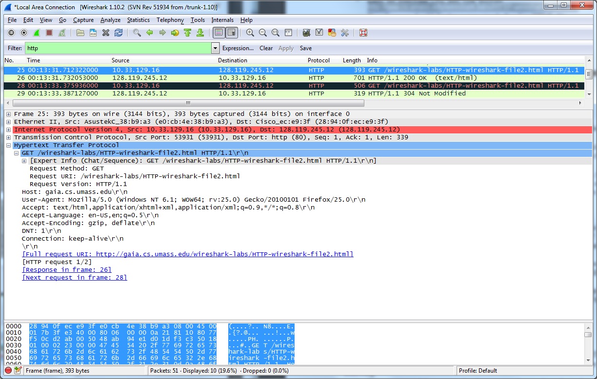


![IMG_0460[1]](https://bedfordsarah.files.wordpress.com/2013/11/img_04601.jpg)
![IMG_0457[1]](https://bedfordsarah.files.wordpress.com/2013/11/img_04571-e1384130785256.jpg)
![IMG_0459[1]](https://bedfordsarah.files.wordpress.com/2013/11/img_04591.jpg)

![IMG_0462[1]](https://bedfordsarah.files.wordpress.com/2013/11/img_04621.jpg)